Contents
What the FEM analysis gives you
For each node of the mesh, a plate or shell analysis produces eight quantities, all per unit width: the membrane forces nxx, nyy and nxy; the bending moments mxx and myy and the twisting moment mxy; and the shear forces vx and vy. Reinforcement is normally placed in two orthogonal directions, x and y, at the top and at the bottom. The question is how much each of those four layers needs, and whether the slab needs shear reinforcement.
The analysis itself is linear-elastic. Designing the reinforcement from it assumes that local plastic redistribution is possible, which is the usual basis of reinforced concrete design.
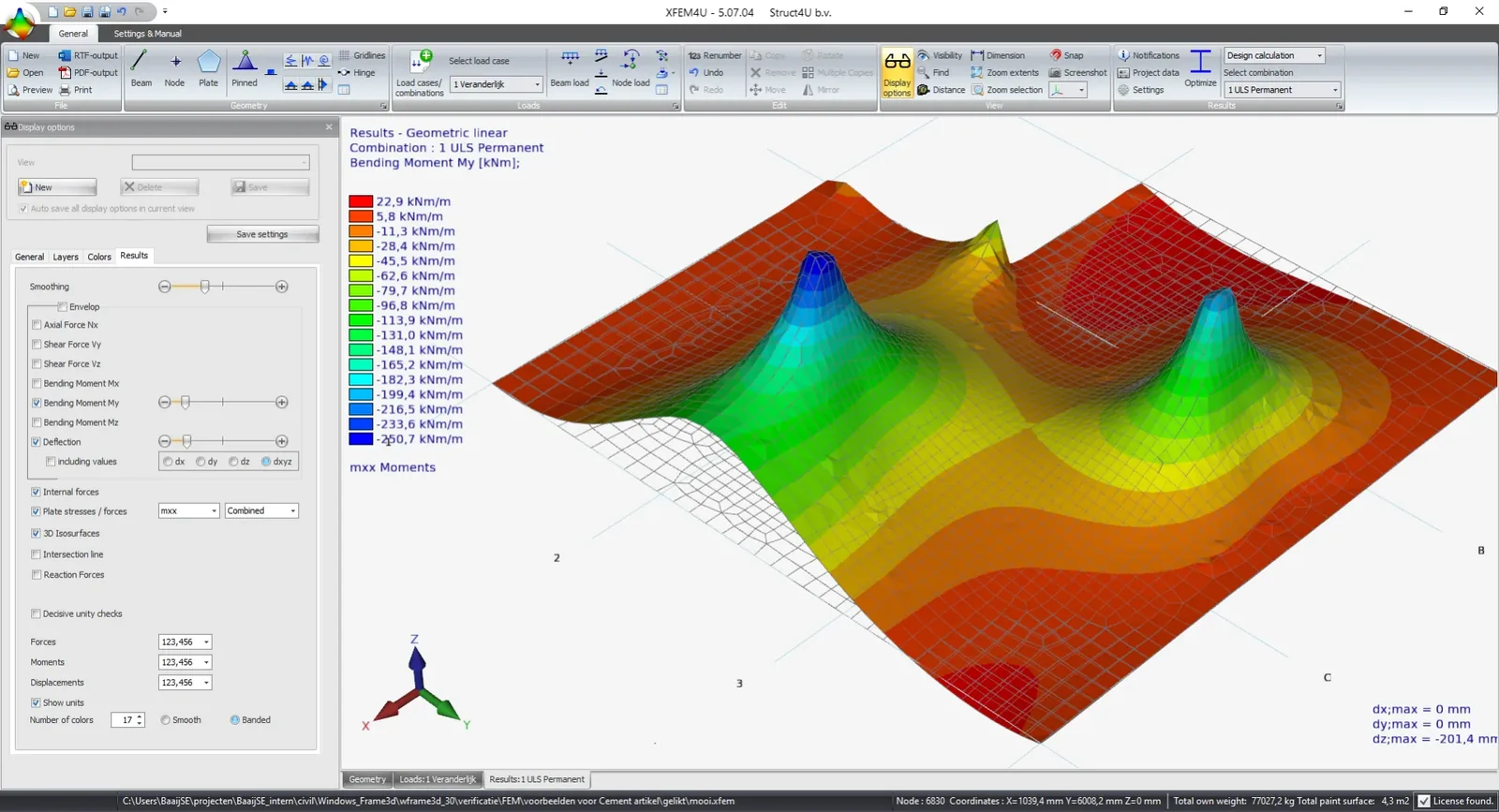
Step 1: in-plane forces and the truss analogy
Normal forces are simple: nxx goes into the x-reinforcement and nyy into the y-reinforcement. The in-plane shear force nxy is not. The usual approach, also behind EN 1992-1-1 Annex F, replaces it by tension in both reinforcement directions and a compression diagonal in the concrete. With the slope of the diagonals written as k (k = 1 for 45°), tension positive:
k = 1 gives the least total reinforcement. When one of the reinforcement forces comes out negative, programs usually just set it to zero. A better answer is to choose k so that this force becomes exactly zero, which saves reinforcement in the other direction.
The y-reinforcement drops from 730 to 620 kN/m, 15 % less, and no x-reinforcement is needed. The price is a higher concrete compression: 715 instead of 660 kN/m.
Worked out in general, every membrane element falls into one of four cases (FIG. 2): reinforcement in both directions, in x only, in y only, or none at all because the element is compressed in every direction. In that last case the larger principal compression is checked against the concrete strength. The transitions between the cases are smooth, which matters for a program that decides at every node.
Step 2: bending and the sandwich model
For moments, most programs use the Wood–Armer method. It is clear and compact, but according to Blaauwendraad and Braam it has three shortcomings: it becomes unsafe with dominant twisting moments and high reinforcement ratios, it says nothing about the concrete compression at the top and bottom of the slab, and it offers no solution when shear reinforcement is needed. That leaves only a thicker slab or a higher concrete class.
The sandwich model proposed by Marti, described in an annex of Eurocode 2 for bridges, splits the slab into three layers (FIG. 3): a top and a bottom shell that carry the moments and the membrane forces, and a core that carries the shear. The moments become a couple of membrane forces in the shells, with lever arm dv between the shell centres.
Each shell is then reinforced as a membrane, with the same four cases, and its concrete compression is checked. The top and the bottom may fall into different cases, with compression diagonals in different directions.
Like Wood–Armer, the three-layer model suits reinforcement ratios that are not too high and twisting that does not dominate, which covers most practical slabs. Its real gains are the check of the concrete compression in both shells and the extension to shear reinforcement.
Step 3: shear reinforcement in plates
In a plate the shear force has a direction. The principal shear force is v0 = √(vx2 + vy2), acting in the direction φ0 with tan φ0 = vy / vx; perpendicular to it the shear force is zero. v0 is compared with the resistance without shear reinforcement, vRd,c from EN 1992-1-1 §6.2.2, using the reinforcement ratio and the normal force in the direction of v0.
Where v0 exceeds vRd,c, the core gets stirrups and its compression diagonals are checked, at an angle θ between about 22° and 45° as in beams (§6.2.3). The diagonals also push the shells apart: each shell gets an extra tensile force ½ v0 cot θ in the direction of v0. That is the plate version of shifting the moment line in a beam, and it adds reinforcement in both shells.
Because vRd,c depends on the reinforcement ratio, the calculation runs twice: first the shell reinforcement from the moments, then per node the decision on shear reinforcement, which in turn adds to the shells. The authors conclude that stopping after this second pass is safe. The crack width check has a place in the same iteration.
Around columns, use the punching check
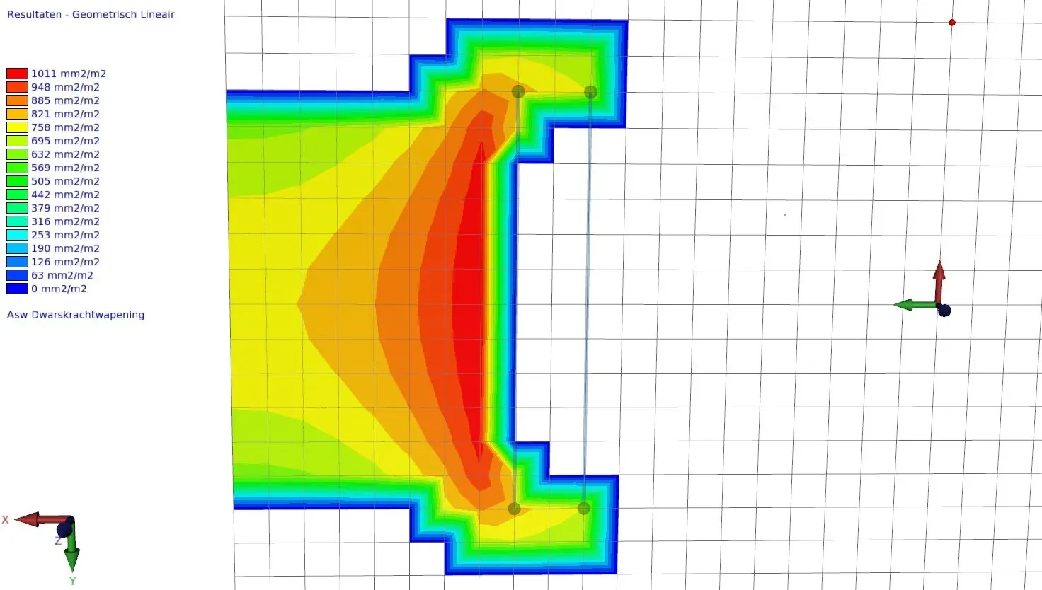
The model also reports shear reinforcement around columns, where the designer does not need it, because the punching check of §6.4 applies there. That check gives far less vertical reinforcement: it lets the compressed bottom shell above the column carry a large part of the shear, while in the three-layer model the core carries all of it. Around a column head the stress state is no longer that of a plate but axisymmetric and three-dimensional. XConstruct has a punching module for this check.
Elsewhere, shear reinforcement tends to appear in small, local areas: where a supporting wall ends in the middle of a slab, or in the obtuse corner of a skew bridge deck. Across large areas, a thicker slab or a higher concrete class is the practical answer.
What the XFEM4U report shows
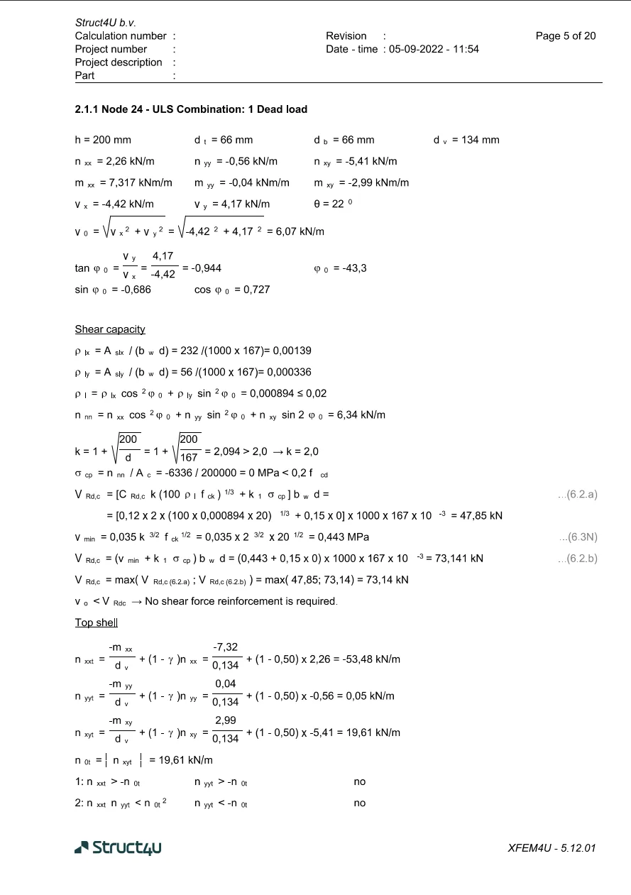
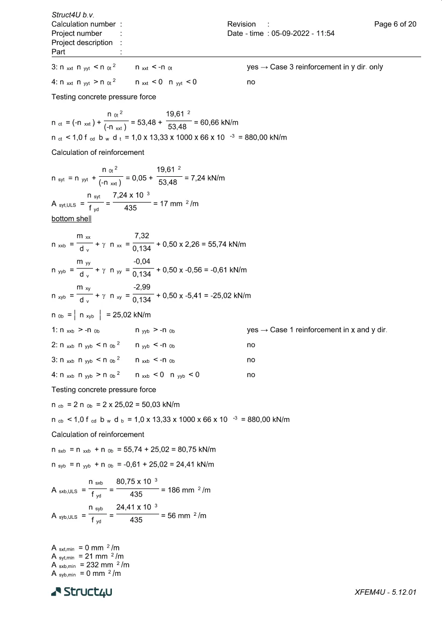
XFEM4U prints the whole procedure per node, so every step can be checked. The two report pages below show node 24 of a 200 mm slab, with shell thicknesses dt = db = 66 mm and dv = 134 mm.
- Shear: v0 = √(4.42² + 4.17²) = 6.07 kN/m, against vRd,c = 73.1 kN per metre, the larger of (6.2.a) and (6.2.b) with vmin from (6.3N). No shear reinforcement is needed.
- Top shell: nxx,t = −53.48, nyy,t = 0.05 and nxy,t = 19.61 kN/m: case 3, reinforcement in y only, 17 mm²/m. The concrete compression, 60.66 kN/m, is far below 880 kN/m.
- Bottom shell: case 1, reinforcement in both directions: 186 mm²/m in x and 56 mm²/m in y.
- Minimum reinforcement is applied last, for example 232 mm²/m at the bottom in x.
Why the element type matters
Reliable shear reinforcement needs reliable shear forces. XFEM4U uses a hybrid plate element: a quadrilateral with 12 degrees of freedom whose displacements are assumed only along its edges, while the moments inside it vary quadratically, described by 17 moment parameters that are in equilibrium with each other. The element follows from minimising the complementary energy. Such elements give a clear distribution of moments over the element and trustworthy shear forces; Rijkswaterstaat’s engineering departments already used them in the 1970s.
Plates in XFEM4U are calculated geometrically linear; second-order effects are taken into account for the beams.
- J. Blaauwendraad and R. Braam, “Wapenen van schijven en platen” (long version, in Dutch), Cement 2021/8 (opens in a new tab); PDF, 26 pages.
- P. Marti, “Design of Concrete Slabs for Transverse Shear”, ACI Structural Journal, 1990.
- R.H. Wood, “The reinforcement of slabs in accordance with a predetermined field of moments”, Concrete, February 1968; G.S.T. Armer, correspondence, Concrete, 1968.
- EN 1992-1-1:2004 §6.2.2, §6.2.3, §6.4 and Annex F; EN 1992-2:2005 Annex LL (in the Netherlands NEN-EN 1992-1-1 and NEN-EN 1992-2 with their national annexes).
- Struct4U, “Calculation plate reinforcement XFEM4U”, struct4u.com, 10 June 2022: the post this article replaces.
Originally published on struct4u.com on .